
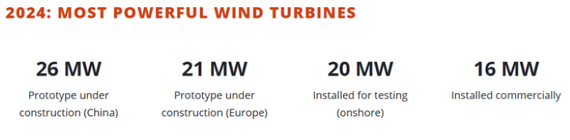
The offshore wind industry is pushing beyond familiar limits. Turbines rated at 15MW and above are no longer prototypes — they are entering commercial deployment. Designs exceeding 20MW are already in development, bringing new structural challenges that cannot be solved by simply scaling up past solutions.
Larger turbines mean longer blades, taller towers, and greater forces acting on every component. Dynamic wind loads, wave-induced vibrations, and cyclic stresses are intensifying, testing the limits of existing verification methods. The forces at play are complex, and failure modes that were once secondary concerns — fatigue in welds, buckling in slender structures, joint integrity under fluctuating loads — are now primary design risks.
Traditional verification workflows struggle to keep pace. Hand calculations and static code checks no longer capture the whole picture. Engineers must validate designs against industry standards while ensuring fatigue resistance, structural stability, and material optimisation. Without efficient verification, projects face unnecessary delays, excessive conservatism, and overlooked structural vulnerabilities.
This article examines the practical engineering challenges of next-generation wind turbines and the role of automated, multi-standard verification in delivering safe, compliant, and cost-effective designs.
1. The New Engineering Realities of 15MW+ Wind Turbines
The next generation of offshore wind turbines brings unprecedented engineering challenges. Larger rotors, taller towers, and increased dynamic loads push structural integrity to new limits. Initially developed for smaller turbines, traditional verification methods now face fundamental limitations.
Increased Loads & Fatigue Cycles
Rotor diameters exceeding 250 meters mean longer blades and higher centrifugal forces. Each revolution introduces cyclic stresses that accumulate over time, making fatigue failures a critical concern. The aerodynamic loads at blade-tip speeds approaching 90 m/s amplify stress concentrations at the blade root and hub connections, requiring more precise validation of fatigue life and crack propagation.

Source: U.S. Department of Energy
As tower heights surpass 150 meters, bending moments from wind and wave interactions increase buckling risks in the tower shell and support structures. These effects are even more pronounced in floating wind designs, where platform motion introduces additional cyclic loading.
New Materials & Manufacturing Constraints
The industry is exploring hybrid steel-composite structures to balance weight and strength, but fatigue resistance in these materials lacks standardised verification methods. Transitioning to new materials requires updated buckling, fatigue, and joint integrity assessments beyond what current codes provide.
Verification Gap
Existing FEA-based verification struggles with multi-scale fatigue assessments, particularly in welded joints and bolted connections. Global and local buckling criteria must be revisited as tower geometries push past conventional design assumptions.
To address these challenges, standards like DNV-RP-C203 (fatigue) and AISC 360-22 (steel structures) must evolve. Without updated verification tools, engineers risk overdesign, unexpected failures, and project delays — all costly in an industry scaling at this pace.
2. Floating Wind: The Next Structural Verification Bottleneck
Floating wind is moving from concept to large-scale deployment. Unlike fixed-bottom turbines, which are limited to depths of 50-60 meters, floating wind farms can be installed in waters exceeding 100 meters, accessing stronger and more consistent wind resources. The challenge? These structures operate in a fundamentally different loading environment, where traditional verification approaches fall short.

Source: SDC Verifier
Engineering Challenges in Floating Wind Verification
Fixed-bottom turbines are anchored directly to the seabed, but floating platforms rely on mooring systems and hydrodynamic stability. This introduces highly dynamic loading conditions that must be accounted for in structural verification:
· Hydrodynamic forces, such as waves, currents, and wind-driven motions, create complex, non-uniform stress distributions that are difficult to predict.
· Mooring fatigue and station-keeping loads — continuous oscillations introduce cyclic stress patterns not present in traditional offshore foundations.
· Coupled platform-turbine interaction — platform movement affects wind turbine dynamics, requiring integrated analysis across multiple disciplines. Standard verification tools often oversimplify these interactions, leading to errors in load predictions.
Why Verification is Slowing Adoption
Floating wind requires compliance with multiple overlapping industry standards, including ISO 19902, DNV-ST-0119, and API RP 2A. These standards were primarily designed for fixed offshore platforms and do not fully address the complexities of floating wind systems.
As a result, engineers must conduct separate verification steps for platform hydrodynamics, structural fatigue, and mooring integrity — slowing down certification timelines and leading to overdesign as a safeguard against uncertainty. Floating wind risks unnecessary cost inflation and deployment delays without a more streamlined verification approach.
3. Why Standards Are Lagging Behind
The rapid growth of wind turbine capacity has outpaced the evolution of industry standards. Many structural verification codes today — AISC 360-22, Eurocode 3, API RP 2A — were initially developed for smaller-scale offshore platforms and onshore steel structures. These standards still form the foundation for compliance but do not fully address the complexities of 15MW+ turbines.
Legacy Standards Were Not Designed for 15MW+ Turbines
As turbine dimensions increase, so do fatigue, buckling, and material performance challenges. Existing codes:
· Fatigue calculations — Many current standards use fatigue assessment models calibrated on smaller structures. The scaling effects on large-diameter tubular joints in modern towers introduce higher stress concentrations that legacy fatigue formulas fail to capture.
· Buckling criteria — Modern turbine towers are taller and more slender, making them more susceptible to local and global buckling. Hybrid steel-composite materials, now being explored for weight reduction, require new verification methodologies that are not yet fully covered in standards.
Inconsistencies in Global Compliance Requirements
A single wind turbine design must be verified differently depending on where it will be installed:
· DNV and Eurocode in Europe
· AISC in the U.S.
· ISO-based frameworks in Asia
This forces engineers to conduct redundant verification processes, increasing design complexity, certification costs, and project timelines.
Key Areas Where Compliance Must Evolve
· Weld fatigue life prediction — Current methods lack precision for large-diameter tubular connections, leading to either overdesign or premature fatigue failures.
· Buckling verification for hybrid materials — Steel-composite structures behave differently under load, requiring updated stability checks.
· Floating wind compliance — Coupled wind-wave-current loading must be integrated into verification frameworks to ensure realistic fatigue and stability assessments.
Until standards catch up, engineers must bridge the gap with more advanced verification methods to ensure safe, efficient, and cost-effective turbine designs.
4. Smarter Structural Verification: A Practical Engineering Approach
Structural verification becomes a significant bottleneck as wind turbines scale beyond 15MW and floating wind expands into deeper waters. Traditional compliance methods — manual calculations, disconnected tools, and repetitive code checks — were manageable for smaller turbines, but they no longer keep pace with modern designs. Engineers need a more thoughtful, integrated approach that ensures accuracy while reducing inefficiencies.
Moving from Manual Verification to Automated Compliance Workflows
Current verification processes often involve:
· Manually checking fatigue, buckling, and load-bearing capacity across multiple standards.
· Switching between CAD, FEA, and compliance tools leads to inconsistencies.
· Generating reports manually, delaying certification and decision-making.
These inefficiencies increase engineering workload, risk of human error, and project costs. A streamlined approach is essential to keep up with evolving design complexities.
How Modern Verification Tools Accelerate Engineering Workflows
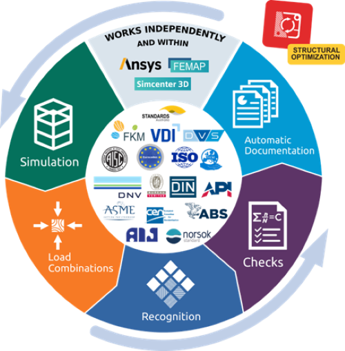
Structural design and analysis software SDC Verifier integrate directly with FEA tools like Ansys, Simcenter 3D, and Femap, enabling:
· Automated fatigue and buckling checks across multiple standards in a single workflow.
· Instant detection of critical structural elements (welds, joints, plates).
· One-click compliance reporting, cutting documentation time from weeks to minutes.
Example Workflow Using SDC Verifier
1. Import FEA results (loads, stresses, displacements).
2. Automatically detect welds, joints, beams, plates, and buckling-sensitive areas.
3. Perform compliance checks for fatigue, ultimate limit states, and buckling.
4. Generate certification-ready reports instantly instead of spending days compiling results manually.
Why This Matters for 15MW+ and Floating Wind Turbines
· Eliminates verification bottlenecks, accelerating project approval.
· Reduces overdesign, ensuring optimal material use without compromising safety.
· Future-proofs turbine designs, ensuring compliance as standards evolve.
By integrating verification directly into the engineering workflow, automated tools allow teams to focus on innovation and execution rather than repetitive calculations and compliance paperwork.
The Engineering Race for Next-Gen Wind Energy
The shift to 15MW+ and floating wind turbines is no longer a future challenge — it is happening now. As turbine designs scale, structural verification must evolve to keep projects on schedule, control costs, and ensure long-term reliability.
Structural analysis and design software SDC Verifier enable engineers to automate compliance checks, integrate FEA results directly into design workflows, and generate certification-ready reports in minutes. These capabilities eliminate bottlenecks, ensuring that fatigue, buckling, and global stability challenges are addressed efficiently and accurately.


McMurtry Spéirling defies gravity using fan downforce
What a fun demonstration. I wonder if they were brave enough to be in the car when it was first turned over. Racing fan cars would be an interesting...