Turbine flow design has changed little since their invention in the eighteenth and nineteenth centuries due to the simplicity and power of these devices to extract energy from the movement of a flowing water source.
Turbine flow meters are one of the most commonly used and simplest methods of measuring liquid flow, from water and beer to aggressive chemicals, including ultra-pure water. The variety of turbine flowmeters are based on the mechanics – the physical orientation of the turbine in relation to the fluid flow.
Turbine flowmeters work in two primary ways:
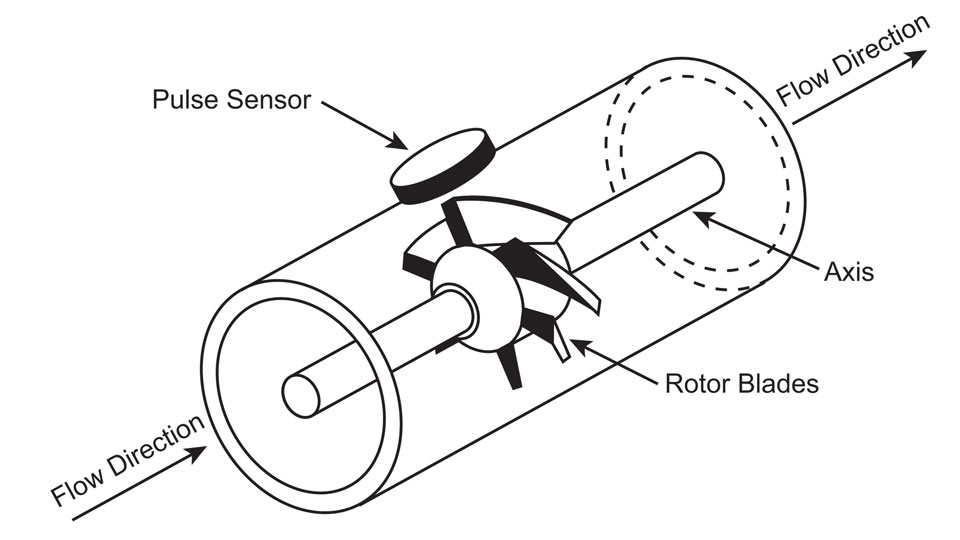
Turbine flowmeters measure the flow rate of a fluid within a pipe or process line by utilising a rotor or turbine that rotates on an axis as the fluid moves across its blades.As the turbine rotates, each blade of the turbine passes a sensor which outputs a pulse signal. The speed at which the turbine rotates is directly proportional to the volumetric flow rate and the number of pulses the total volume passed.
In an axial turbine, the fluid flows along the rotation axis where the fluid enters and exits in the same direction, the fluid striking the angled turbine blades:

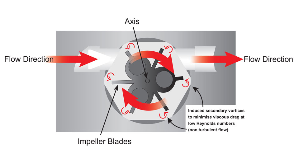
In contrast, fluid flowing through a radial turbine strikes the plain blade in the direction of the tangent or 90° to the rotational axis (hence also referred to as tangential flow):

Titan Enterprises released its first flowmeter sensor in 1981, a turbine device based on the Pelton Wheel design and working principles of the radial turbine.
The Pelton wheel, conceived by Lester Pelton in the 1870’s, is an energy extraction device. Its working principle and design are simple: characterised by a series of distinctive reaction cups, to extract as much energy as possible from the moving liquid, typically to generate electricity. These cups or buckets efficiently capture the momentum of high-velocity water jets, inducing an impulsive force. This force makes the turbine rotate and the rotating shaft runs a generator to produce electricity. As the energy available is only kinetic energy, the Pelton wheel is an example of an impulse turbine.

Such impulse turbines do not require an enclosed case, whereas Radial flow turbines have very different requirements. They must operate in an enclosed pressure chamber and have a linear velocity to flow rate characteristics. Early flowmeters were designed using radial flow onto blades (without reaction cups) with single or multi-jets of liquid. In the last seventy years or so, as accurate measurement of lower flow became a requirement, smaller meters were produced and became known as the generic Pelton wheel flow meter we know today where a single jet impinges a flat blade in an enclosed chamber. There are many design variations of these devices to ensure the best overall performance is attained. The most common system is to simply point a jet radially at a turbine and place the outlet directly opposite the inlet. The turbine has multiple flat blades, from 3 to many more. Titan has utilised up to 12 blades in order to increase the resolution on custom-designed OEM turbine flowmeters, thus improving the accuracy of low volume dispense.
Titan’s mini turbine flowmeter range use the radial flow principle based on the Pelton wheel technique. This well proven method is the ideal way of measuring low rates of flow of low viscosity liquids. For these mini flowmeters, a jet of fluid is directed at a turbine that is mounted on robust low friction sapphire spindle and bearings. The geometry of the turbine and the fluid chamber ensures that the rotational speed of the rotor is proportional to the flow rate through the device. The use of this radial arrangement allows more energy to be imparted into the turbine, so the bearing drag is far less important. Furthermore, because more energy is available the bearings themselves can be a lot stronger, increasing the life of the flowmeter. For larger flows, some of the liquid can bypass the turbine chamber, which then behaves as a “shunt” to the metered fluid. Accuracy is still maintained and the output remains linear.
Axial flow turbines are typically larger and have a higher flow throughput. Generallymore efficient at moving large volumes of air or fluid at lower pressures, they are more suitable for large-scale, high-speed applications where high flow rates and low pressure drops are of prime importance. As such conventional axial turbines are commonly used in thermal power plants, propulsion aircraft engines, wind turbines, and cooling fans for electronics and HVAC systems. Complex designs, manufacture and maintenance of axial turbines can be costly and challenging, becomingincreasingly difficult to manufacture as size is reduced and bearing drag becomes more significant.
On the other hand, radial turbine flowmeters are better suited for applications requiring low flow rates, typically seen in medical applications and laboratory work.
Whilst offering many advantages and ideally suited to handling clean fluids, the turbine flowmeter has one Achilles’ heel: it is very sensitive to changes in liquidReynolds Number; a product of viscosity and density, therefore temperature and, for gas fluids, pressure. Turbine flow devices perform most efficiently with turbulent flow of liquid through the meter. Laminar flow and viscous drag can disrupt the dynamic behaviour of this type of flowmeter which ultimately affect the accuracy of flow measurements. To mitigate this effect, Titan use a hexagon-shaped chamber which permits the formation of vortices that reduce the drag and assist the linearity into the laminar flow region.
Titan’s range of turbine flow meters offers numerous advantages for industry application:
Visit Titan Enterprises’ website for full technical information on Titan’s turbine flowmeters. To discuss your specific OEM application, please contact Titan Enterprises on +44 (0)1935 812790 or email sales@flowmeters.co.uk.


Emergency law passed to protect UK steelmaking
<b>(:-))</b> Gareth Stace as director general of trade body UK Steel, is obviously an expert on blast furnace technology & operation. Gareth...