Anyone familiar with London’s Bank underground station will know that it is a warren of tunnels connecting travellers to the DLR and three underground lines, or five if you count Monument station to which Bank is connected.
The station is a gateway to large parts of London but moving through it can be an arduous task due to its size.
In October 1960, The Engineer reported on a solution to moving vast quantities of people using the Waterloo and City line at Bank, a connection between Waterloo main line station and London’s commercial district with the Bank of England at its centre.
READ THE ORIGINAL ARTICLE HERE
At 1 mile 1,012 yards, the Waterloo and City line is London’s shortest underground route. In 1960 it was carrying over 40,000 passengers a day, most of whom were travelling in the morning and evening rush hours.
“It was obvious even before the war that more trains were needed in the rush hours, but although augmented services were possible from a railway operating point of view, the then existing means of passenger movement to and from street level at the Bank station were inadequate,” said The Engineer.
The rails at Bank are 59 feet below street level, and passengers made their way to and from the railway along a pedestrian tunnel 340 foot long and 13 foot wide, with an overall gradient of 1 in 7.4, the effective slope for pedestrians being reduced to 1 in 14 by five steps at 40 foot intervals.
Prior to WWII, it was proposed to install a three-way escalator to eliminate the long climb up the tunnel – known as ‘the drain’ to sardonic commuters - and Parliament approved the scheme.
The Engineer added that wartime and post-war capital restrictions prevented the scheme from materialising and when, in 1955, the matter was revived, the consulting engineers, Mott, Hay and Anderson (which became Mott McDonald), proposed a different solution.
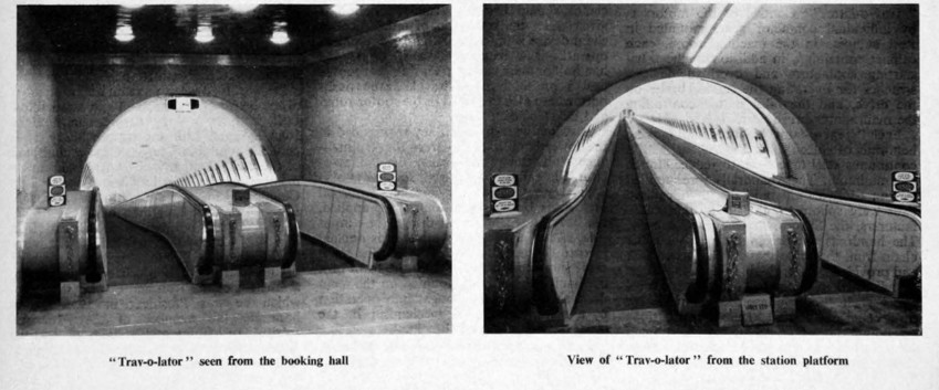
“This was adopted and is now in full operation,” said The Engineer. “The new scheme - using twin travelling pavements, or so-called ‘Trav-o-lators’ - offered numerous advantages over the orthodox escalator for this site. It carried passengers further than escalators could, the existing subway was retained, and the construction involved far less interference with existing underground installations. It was carried out also with less inconvenience to the travelling public.”
Otis Elevator’s Trav-o-lators were installed in a specially driven tunnel with a 16’ 6” internal diameter running approximately parallel with the existing subway. A machinery room and substation at the upper end of the tunnel housed the driving and control gear below the passenger access area. At the top end of the tunnel a new ticket office was built. At the lower end of the tunnel the station was modernised and access to the Trav-o-lators was improved.
The Engineer said: “For the greater part of its length the Trav-o-lator tunnel is, as stated, 16’ 6” diameter, but at the lower end it opens out to 19ft 6In for a distance of 52ft to accommodate the lower landing and return machinery. Beyond this point a further enlargement of I0ft in the diameter provides a circulating area for passengers arriving at the foot of the Trav-o-lators and from the existing subway.”
According to our report, work began with the closing of two short subways at the top leading to streets, and between these two entrances the civil engineering contractors Mitchell Brothers, Sons and Company (latterly Turmag, which folded in 2015), sank a shaft to the level of the Trav-o-lator tunnel.
“Progress was limited by the restricted access to the site, and the fact that much of the work had to be done at night to avoid interference with road traffic. In addition, only a fairly small labour force could be employed owing to the confined space,” said The Engineer.
As soon as the shaft was sunk, a pilot tunnel, 8ft diameter, was driven down the incline. Excavation was done at night, and the spoil had to be hoisted out and removed by lorry until the line of the existing railway tunnel was reached. It then became possible to take away the spoil in rail wagons, again working at night after the passenger service on the line had ceased. Spoil wagons were hauled by one of the passenger cars to the Waterloo end of the line, where they were hoisted some 40ft to main line rail level by the 30-ton lift used for normal railway maintenance, and taken away by surface locomotive for dumping. This route was also used later for taking in the contractor’s heavy materials and the main Trav-o-lator parts.
When the eight foot pilot tunnel had been driven, it was enlarged to the full 16’ 6” diameter, and cast-iron segmental linings, with lead caulked joints, were fixed in position.
While the tunnel was being enlarged, six new openings, each nine feet wide, were cut in the dividing walls between the station platform to facilitate the flow of passengers to and from the Trav-o-lators that were designed for a maximum linear speed of 180 feet per minute. At its maximum speed each Trav-o-lator had a theoretical carrying capacity of 16,200 passengers an hour.


IET sounds warning on AI doll trend
I agree that we need to reduce cooling water demand for servers. And yes, generative AI consumes a large amount. But what about BitCoins? Their...